Lenses
A LENS forms an image by refracting light.
There are TWO types of lenses:
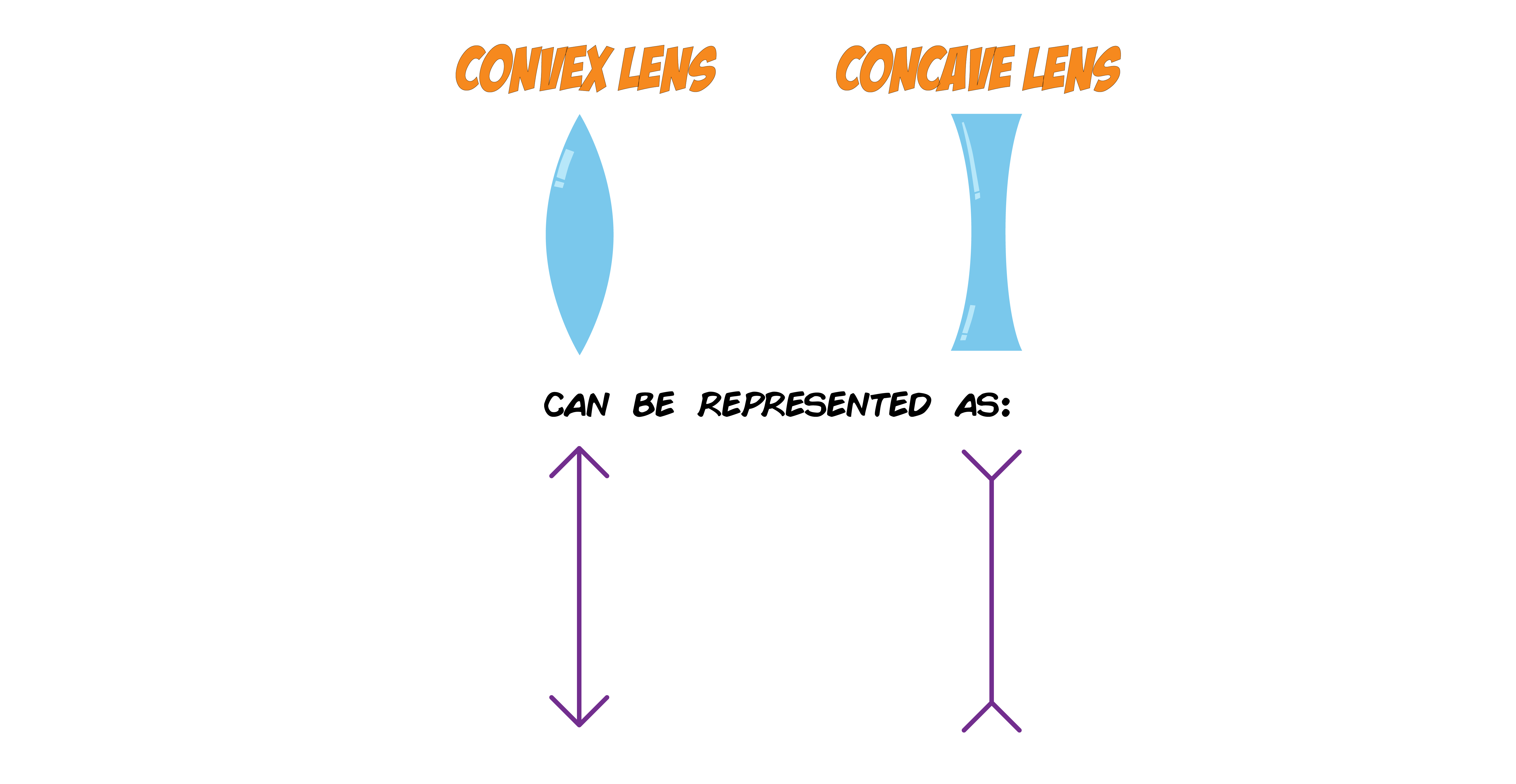
1. CONVEX LENSES are THICK in the middle and THIN on the edges.
2. CONCAVE LENSES are THIN in the middle and THICK on the edges.
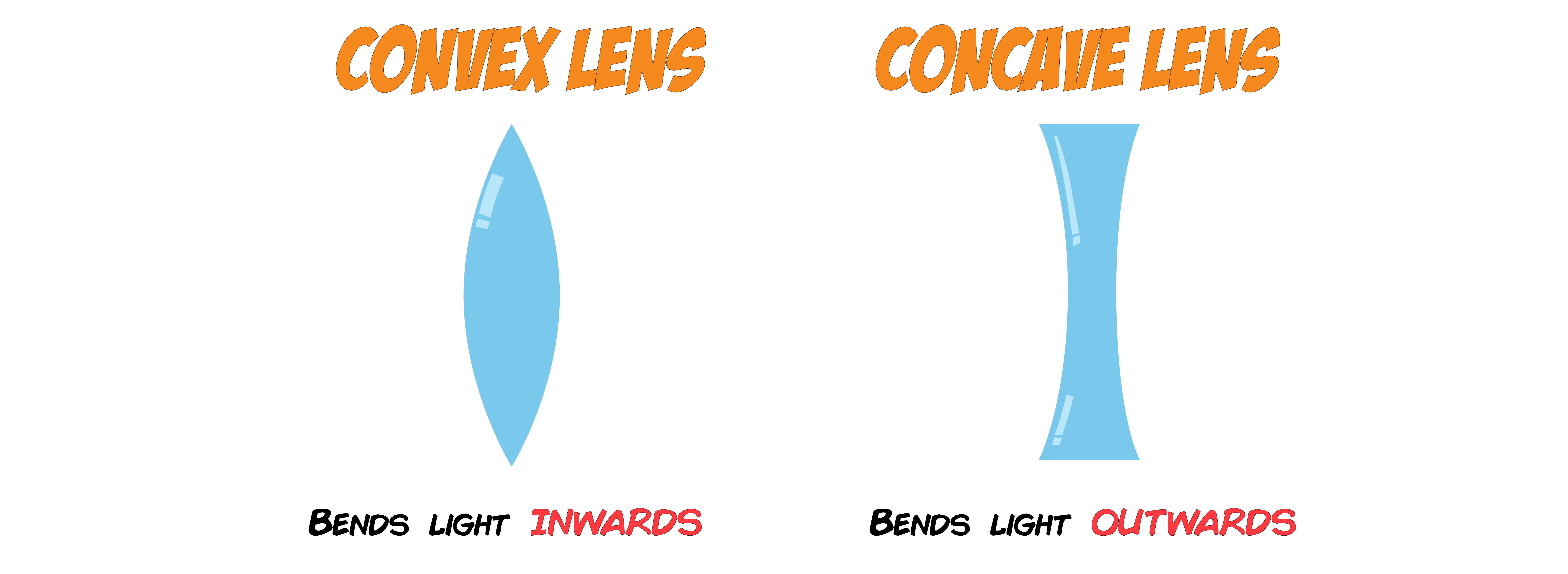
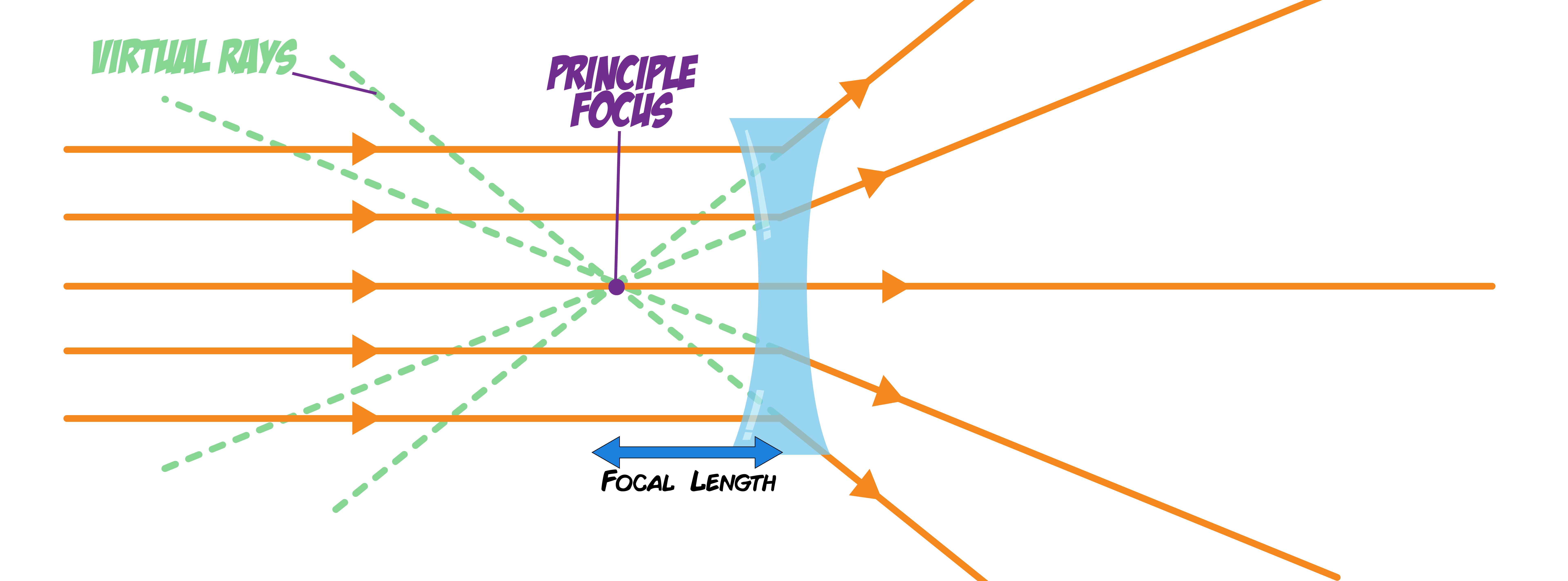
In CONVEX LENSES, light bends INWARDS and rays of light are brought to a focus at the PRINCIPAL FOCUS.
The distance from the lens to the PRINCIPAL FOCUS is known as the FOCAL LENGTH.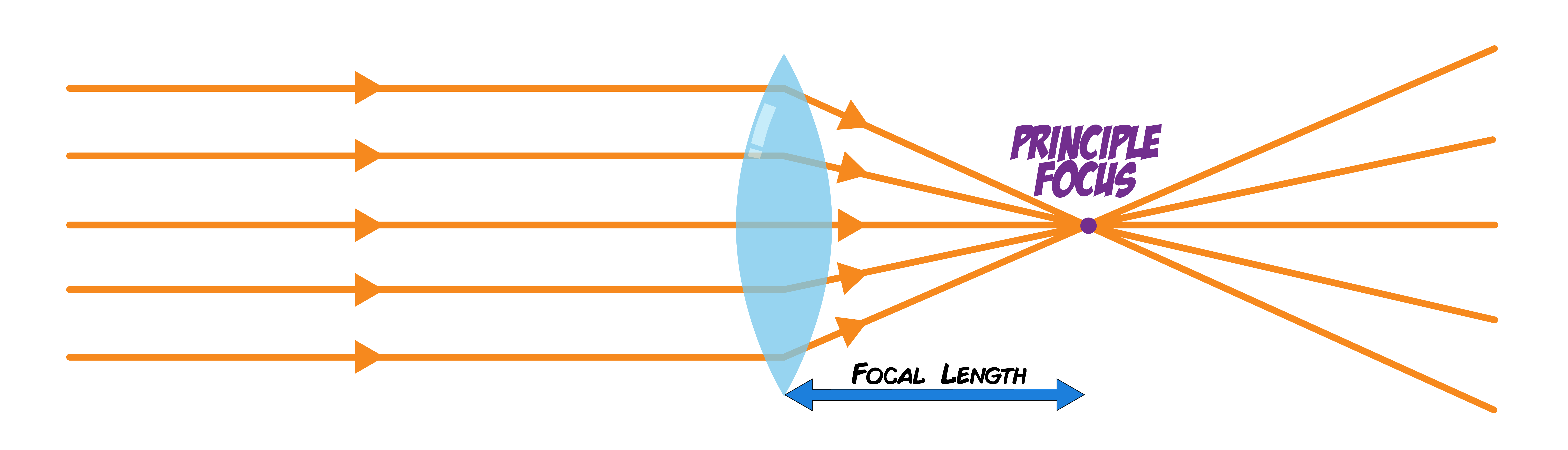
In CONCAVE LENSES, light bends OUTWARDS which means the light rays do NOT meet. The PRINCIPAL FOCUS is the point at which the bent rays APPEAR to come from. These are shown by VIRTUAL RAYS which are represented with DOTTED LINES.
When light from an OBJECT passes through a lens, it can form an IMAGE. There are TWO types of images:
1. REAL IMAGES which can be PROJECTED onto a screen
2. VIRTUAL IMAGES which can NOT be projected onto a screen. They are formed by light rays from objects that do NOT meet, but APPEAR to meet BEHIND the lens with VIRTUAL RAYS (represented by dotted lines)
CONVEX LENSES can produce BOTH REAL and VIRTUAL images. The nature of the image (real or virtual) depends on the position of the object relative to the focal length.
CONCAVE LENSES always produce VIRTUAL images, regardless of the object’s position relative to the lens.
Constructing Ray Diagrams
RAY DIAGRAMS are used to show how IMAGES are formed from light rays leaving an OBJECT and passing through a LENS.
In ray diagrams, CONVEX LENSES are typically represented by a vertical line with arrows pointing outward and CONCAVE LENSES are represented by a vertical line with arrows pointing inward.
Convex Ray Diagrams
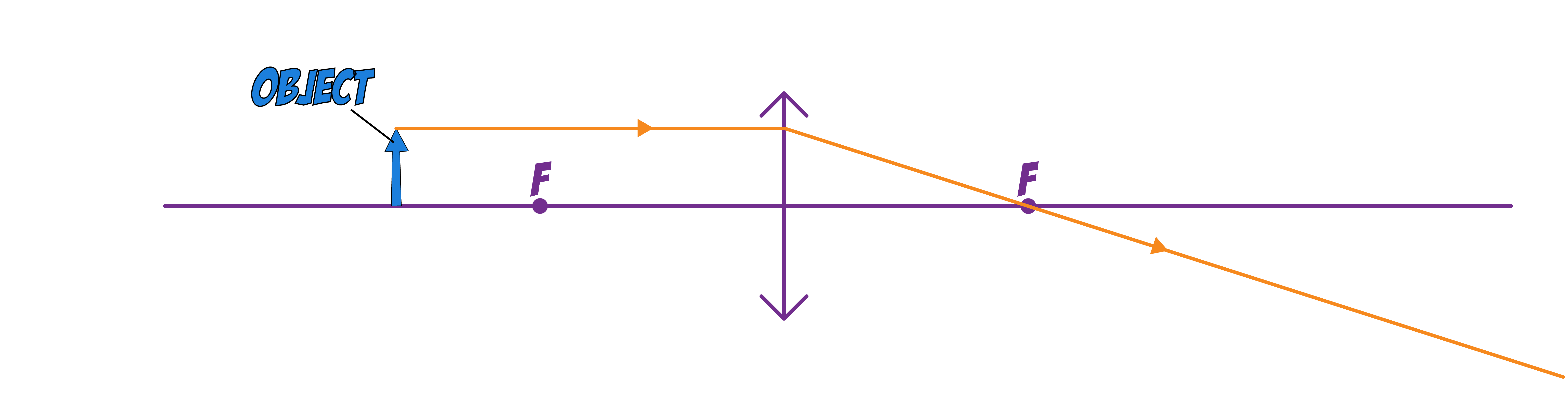
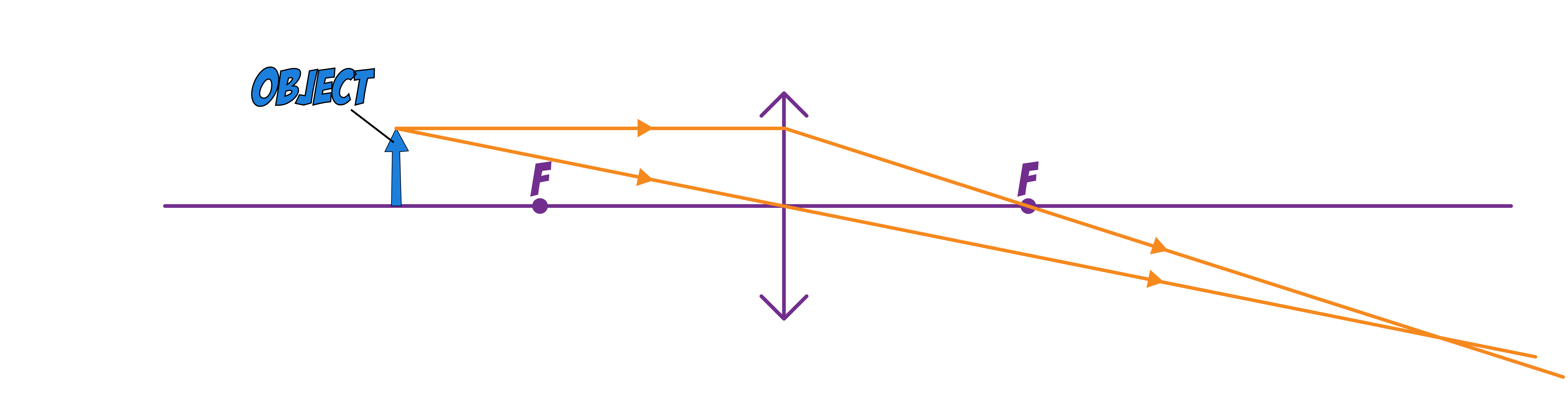
Example 1: When the object is FURTHER than the principle focus
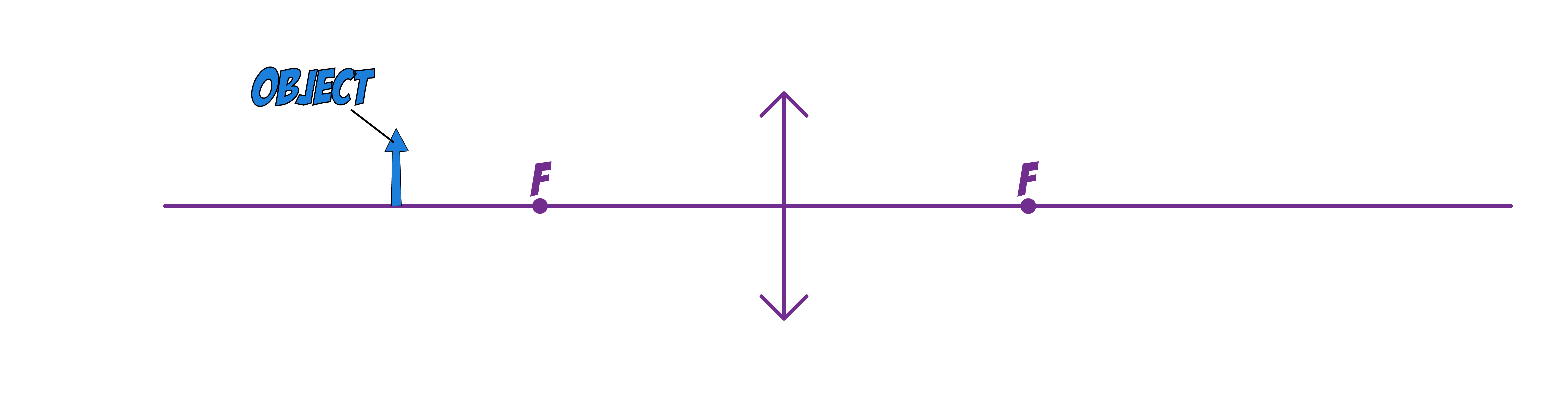
To draw a ray diagram you first start off with an AXIS, PRINCIPAL FOCUS, LENS and the OBJECT.
Then draw the rays using the following steps:
Step 1. Draw a HORIZONTAL ray from the TOP of the object to the LENS.
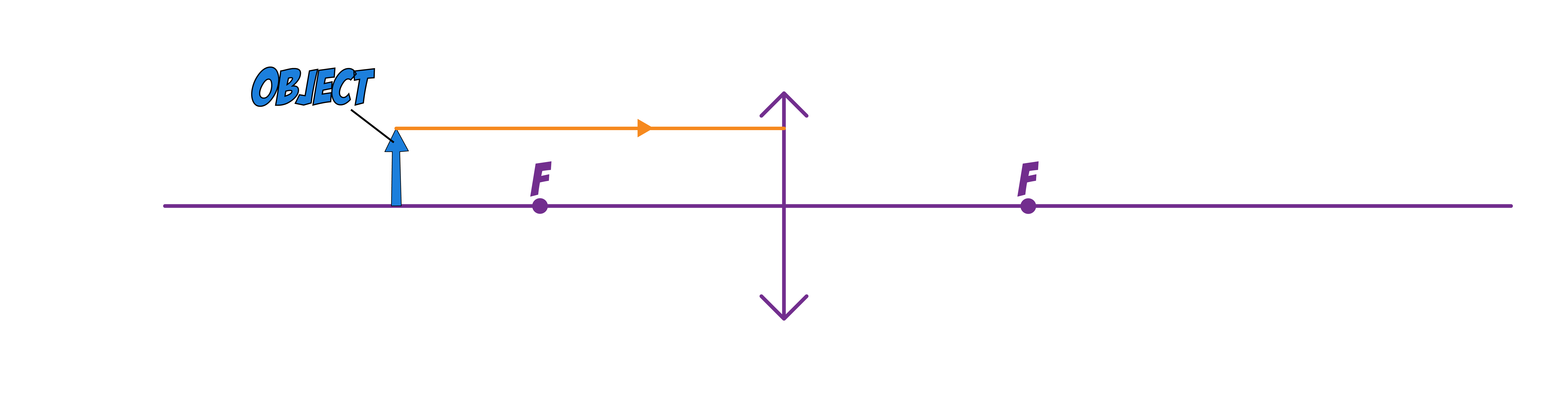
Step 2. Bend the first ray so that it passes through the PRINCIPAL FOCUS and EXTEND it.
Step 3. Draw a SECOND ray from the TOP of the object THROUGH the MIDDLE of the lens and EXTEND it.
Step 4. Draw the IMAGE so that the BOTTOM of the image is on the axis and the TOP is where the TWO RAYS MEET.
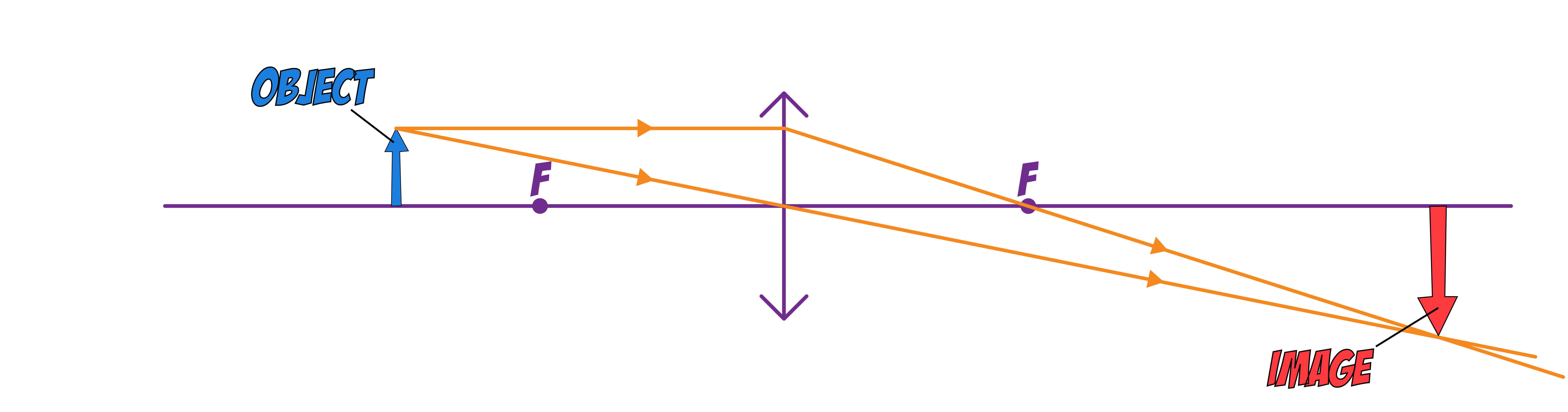
The IMAGE formed can be described as:
1. UPRIGHT or INVERTED
2. LARGER or SAME SIZE or DIMINISHED (smaller)
3. REAL or VIRTUAL
The image in the above example is INVERTED, LARGER and REAL.
Example 2: When the object is BETWEEN the principle focus and the lens.
When you follow the first THREE steps, you will find that the rays get FURTHER so will never meet.
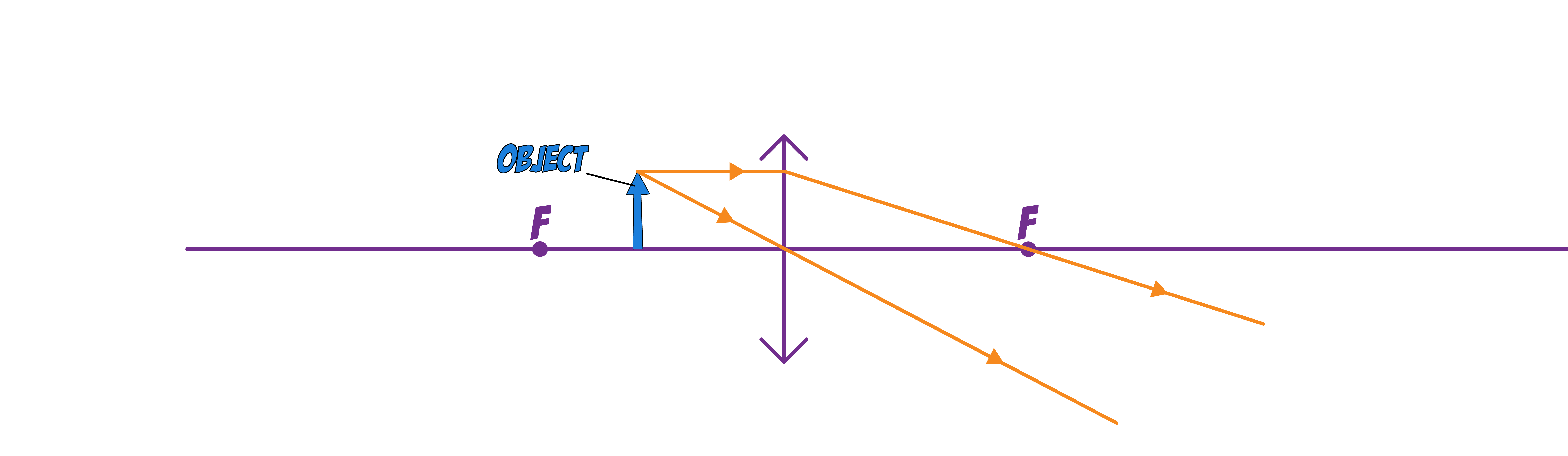
In this situation you would EXTEND the two rays BACKWARDS using DOTTED LINES (virtual rays).
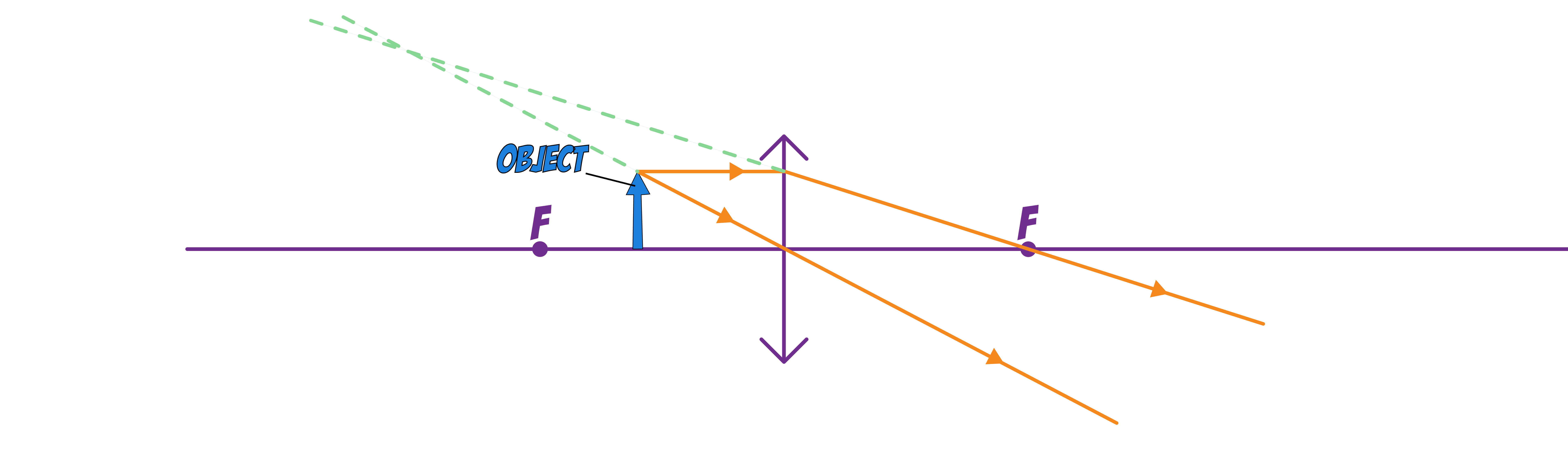
Now follow step 4 and draw the IMAGE so that the BOTTOM of the image is on the axis and the TOP is where the TWO RAYS MEET.
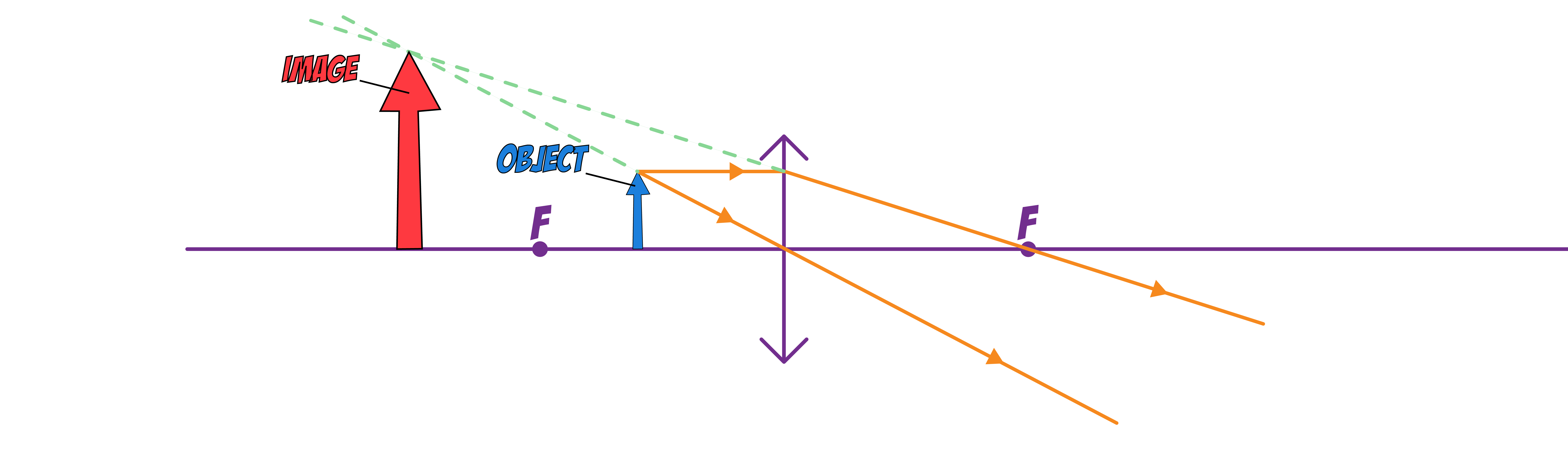
The image in the above example is UPRIGHT, LARGER and VIRTUAL.
Concave Ray Diagrams
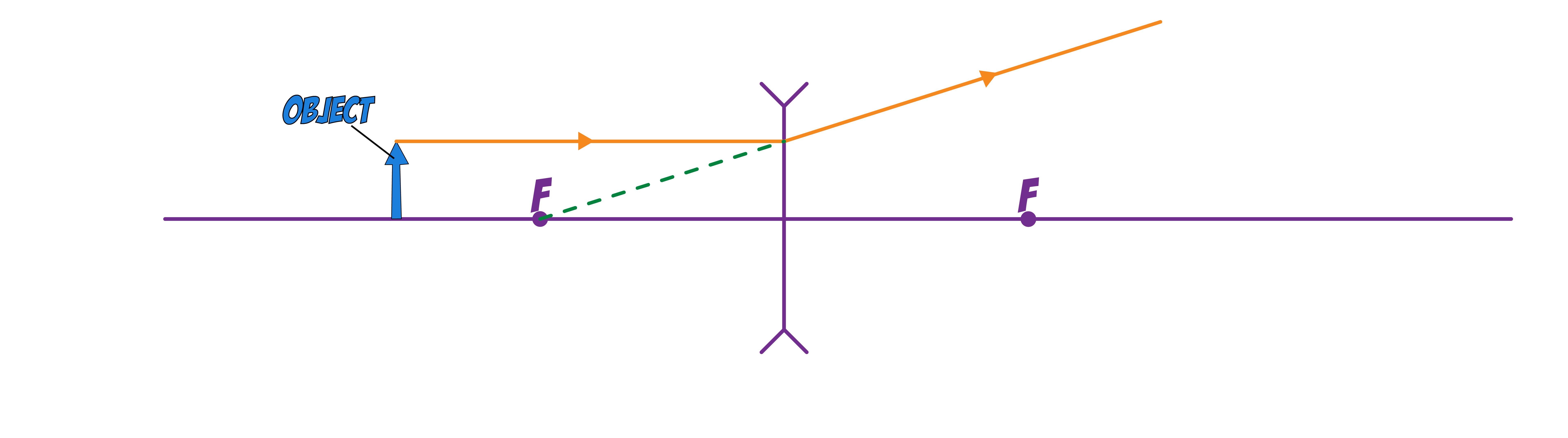
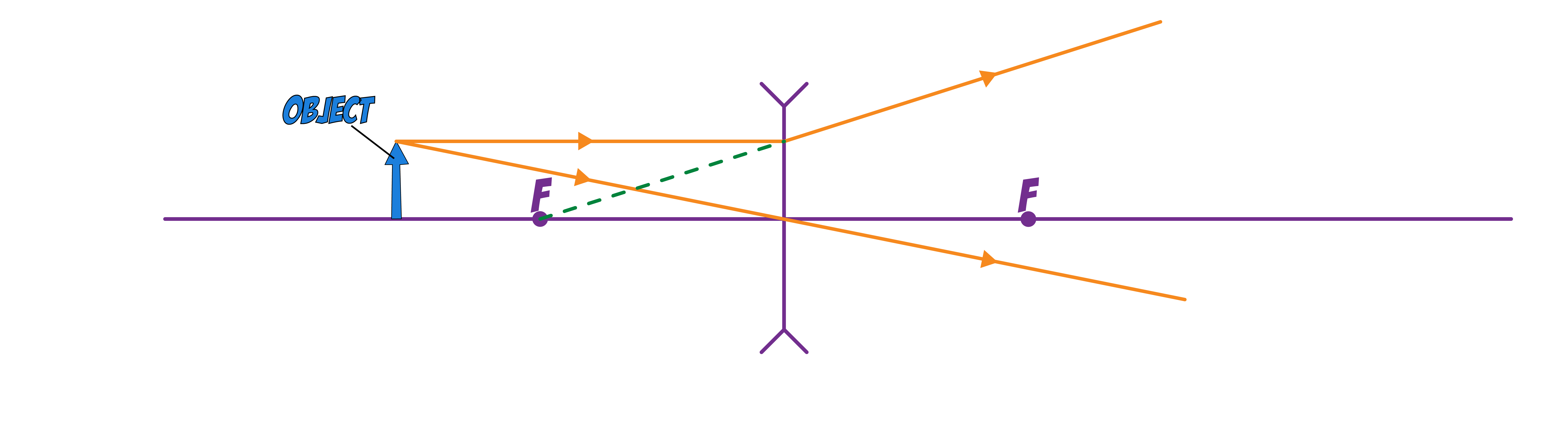
To draw the ray diagram you first start off with an AXIS, PRINCIPAL FOCUS, LENS and the OBJECT.
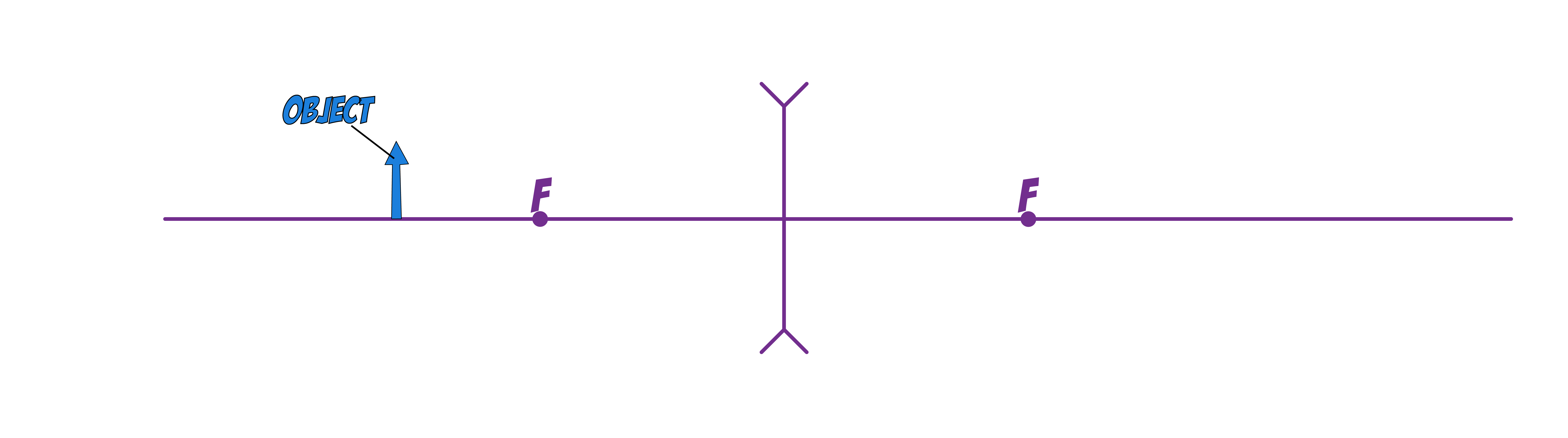
Step 1. Draw a HORIZONTAL ray from the TOP of the object to the LENS.
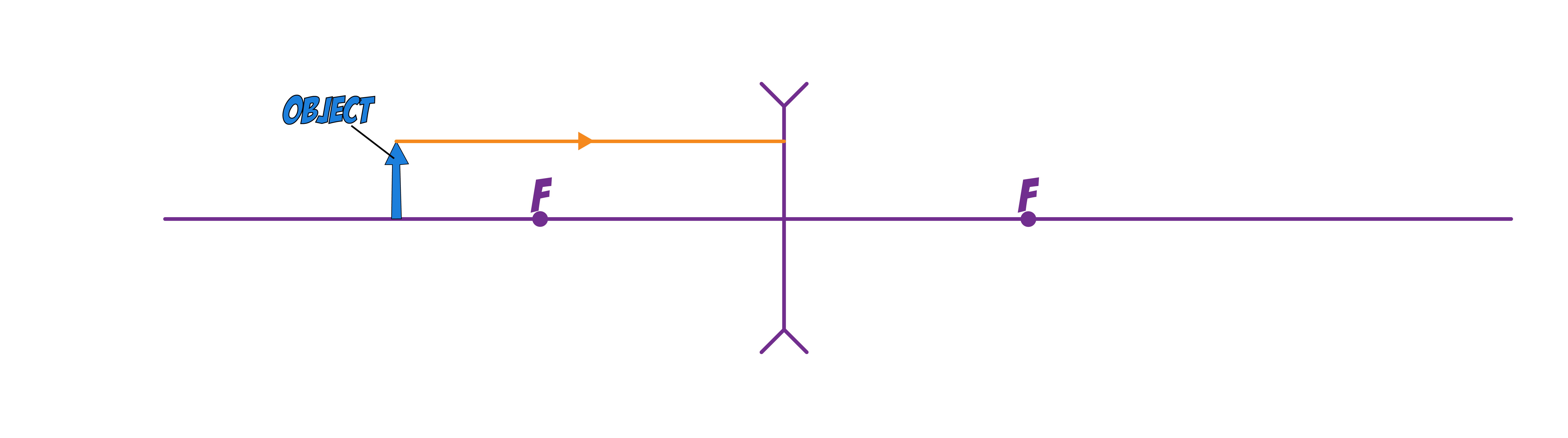
Step 2. BEND the ray and EXTEND it BACK using DOTTED LINES (virtual rays) so that is passes through the PRINCIPAL FOCUS BEHIND the lens.
Step 3. Draw a SECOND ray from the TOP of the object THROUGH the MIDDLE of the lens and EXTEND it.
Step 4. Draw the IMAGE so that the BOTTOM of the image is on the axis and the TOP is where the TWO RAYS MEET.
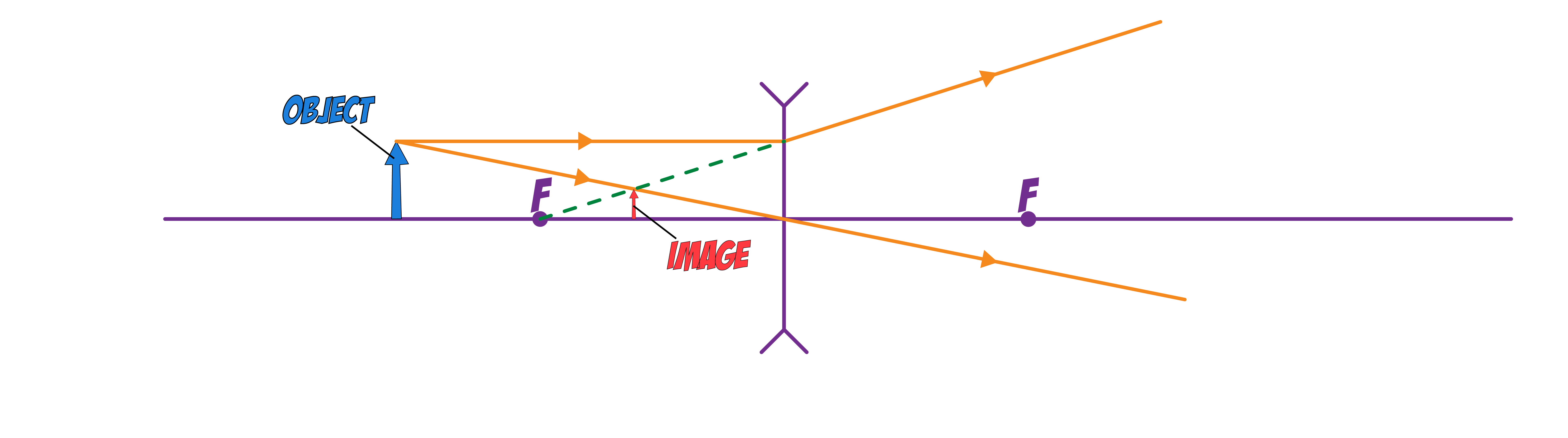
The image in the above example is UPRIGHT, DIMINISHED and VIRTUAL.
Magnification
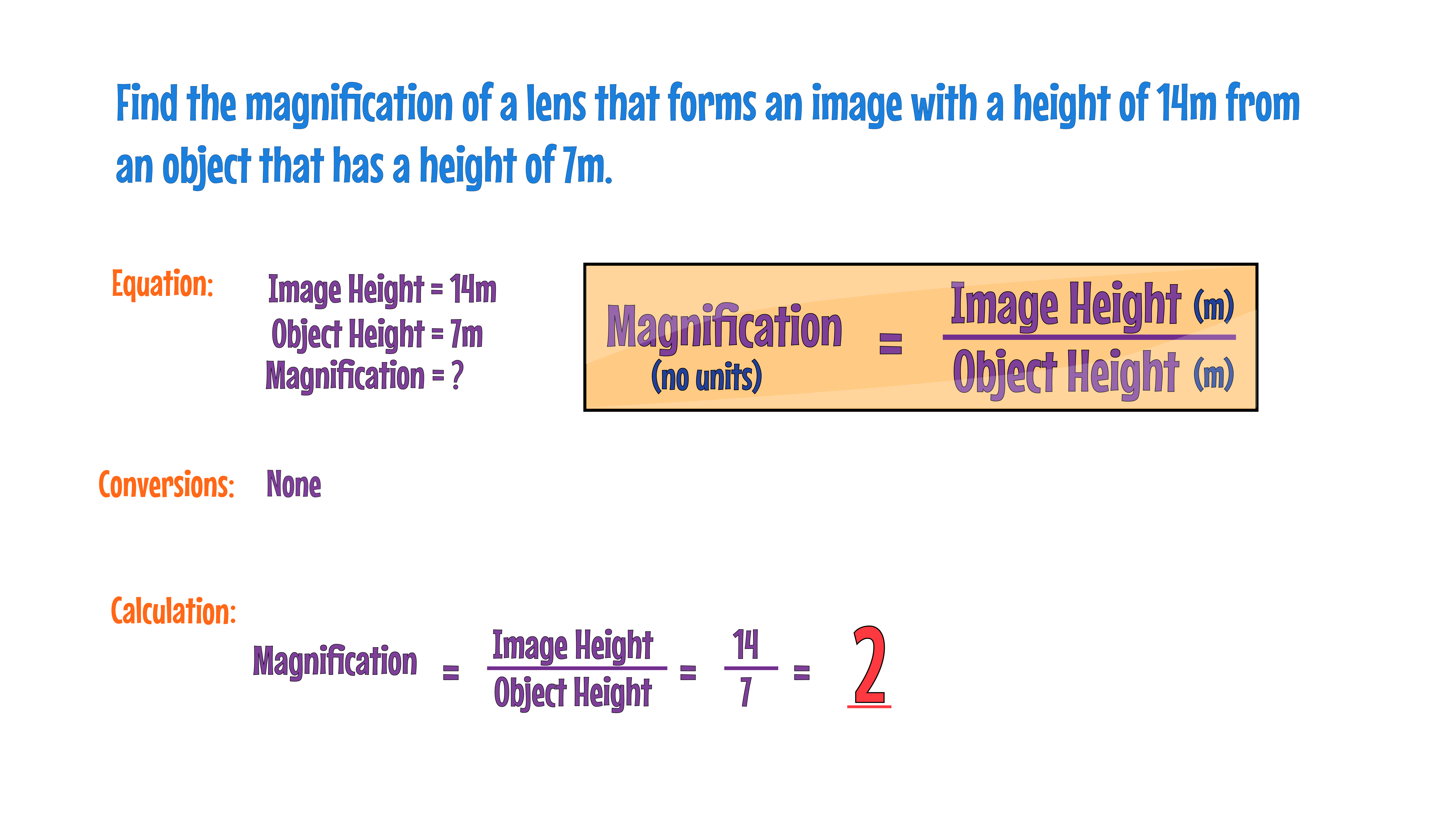
MAGNIFICATION of a lens tells you how much larger or smaller the image is compared to the object. It is calculated using the formula:

Magnification is a ratio and therefore has NO UNITS. Both image height and object height should be measured in the SAME UNITS, eg. millimetres (mm), centimetres (cm) or metres (m).