
Resistors and I-V Graphs
RESISTORS are components in an electrical circuit that change the CURRENT (I) flowing through due to their RESISTANCE (R).
For some RESISTORS, the RESISTANCE remains CONSTANT but in others it can CHANGE as the current changes.
The resistance of many COMPONENTS such as lamps, diodes, thermistors and LDRs is NOT constant; it also changes with the current through the component.
You can use I-V graphs to see how RESISTANCE changes with current in a component.
I-V GRAPHS
There are THREE types of I-V graphs you need to know:
1. OHMIC CONDUCTORS
The CURRENT through an ohmic conductor (at a constant temperature) is DIRECTLY PROPORTIONAL to the POTENTIAL DIFFERENCE across the resistor.
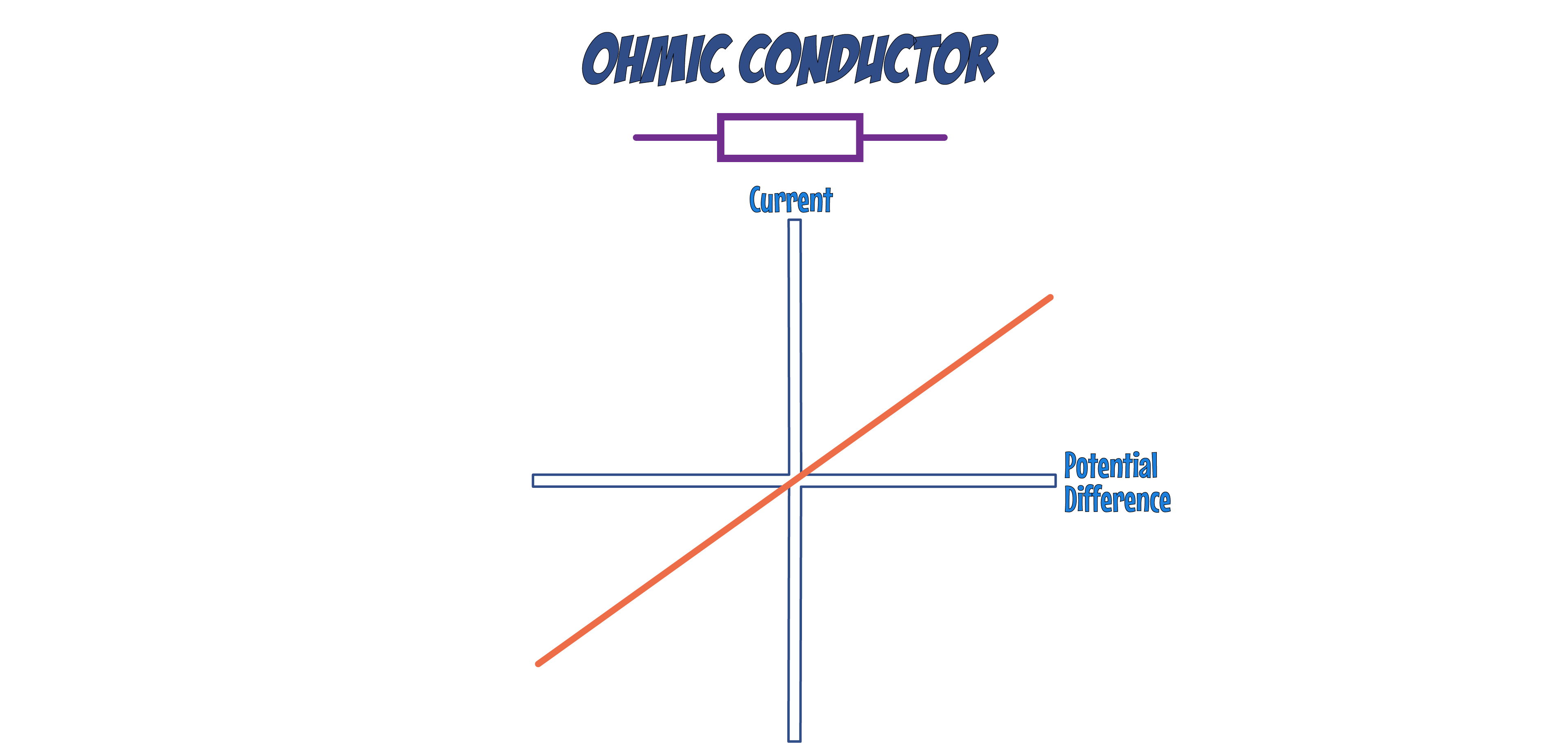
This is shown on the graph as a STRAIGHT LINE through the ORIGIN.
This means that the RESISTANCE remains CONSTANT as the current changes.
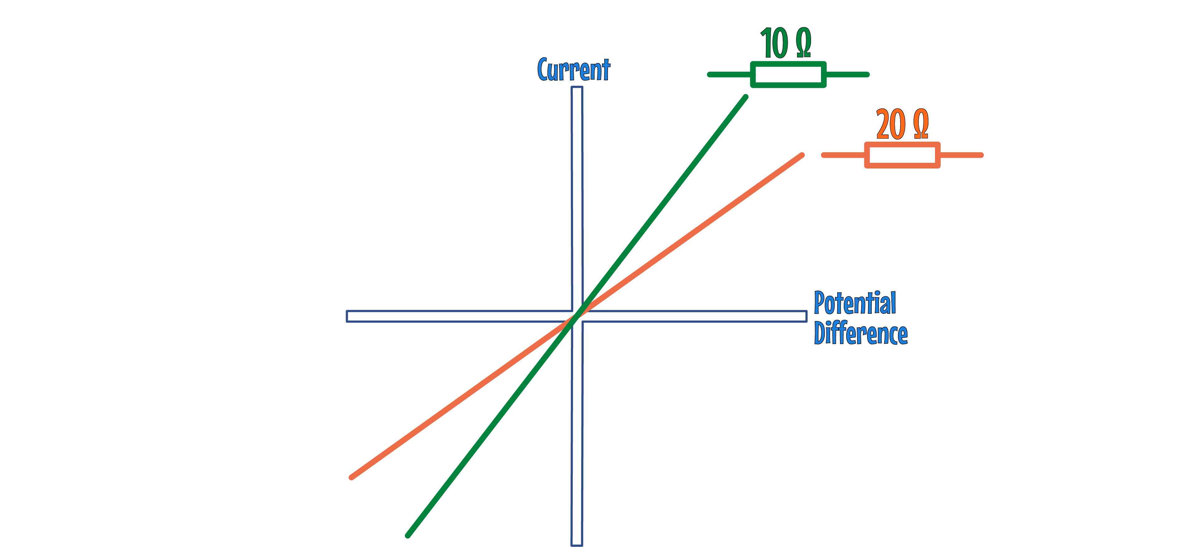
The STEEPER the line, the LOWER the RESISTANCE.
2. FILAMENT LAMP
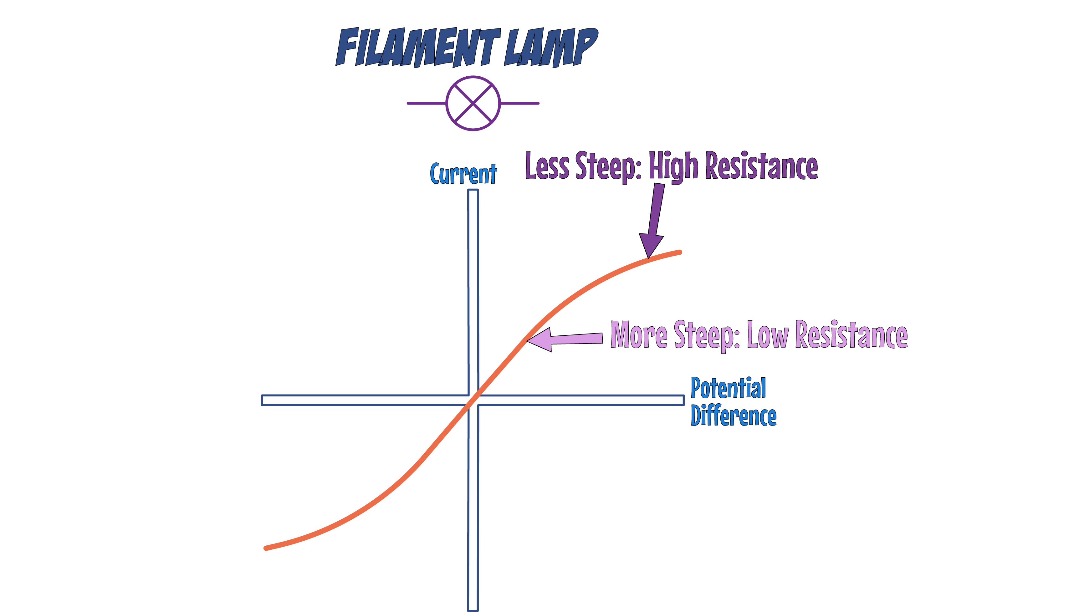
At low potential differences, there is a straight portion on the graph which means the resistance is CONSTANT; the graph curves at higher potential differences.
As the potential difference INCREASES, the gradient (steepness) of line DECREASES, which shows that RESISTANCE is INCREASING.
This is because the FILAMENT in the bulb gets HOTTER, which happens as more current passes through it.
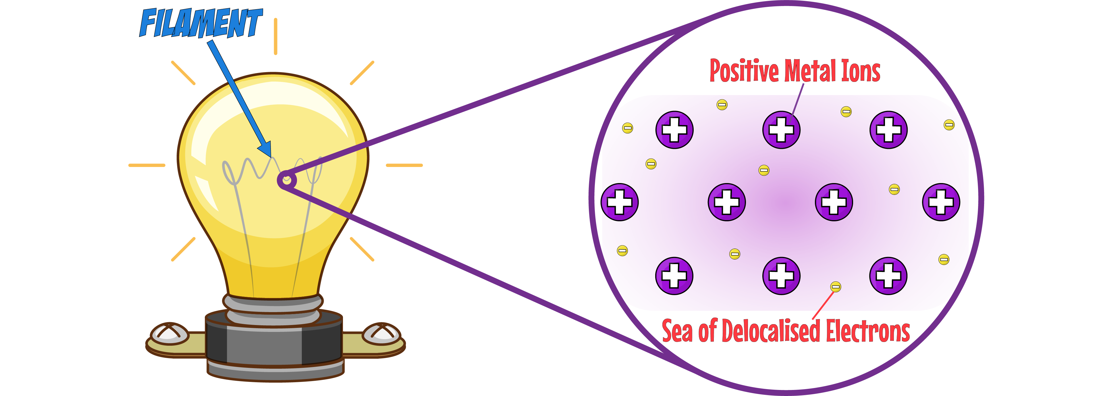
The filament is a METAL which means it contains METAL IONS and DELOCALISED ELECTRONS in its structure.
When the temperature of the filament INCREASES, the metal ions VIBRATE leading to MORE COLLISIONS between the IONS and ELECTRONS which INCREASES RESISTANCE.
3. DIODE
Diodes allow current to flow in only ONE DIRECTION, and have a HIGH RESISTANCE in the opposite direction.
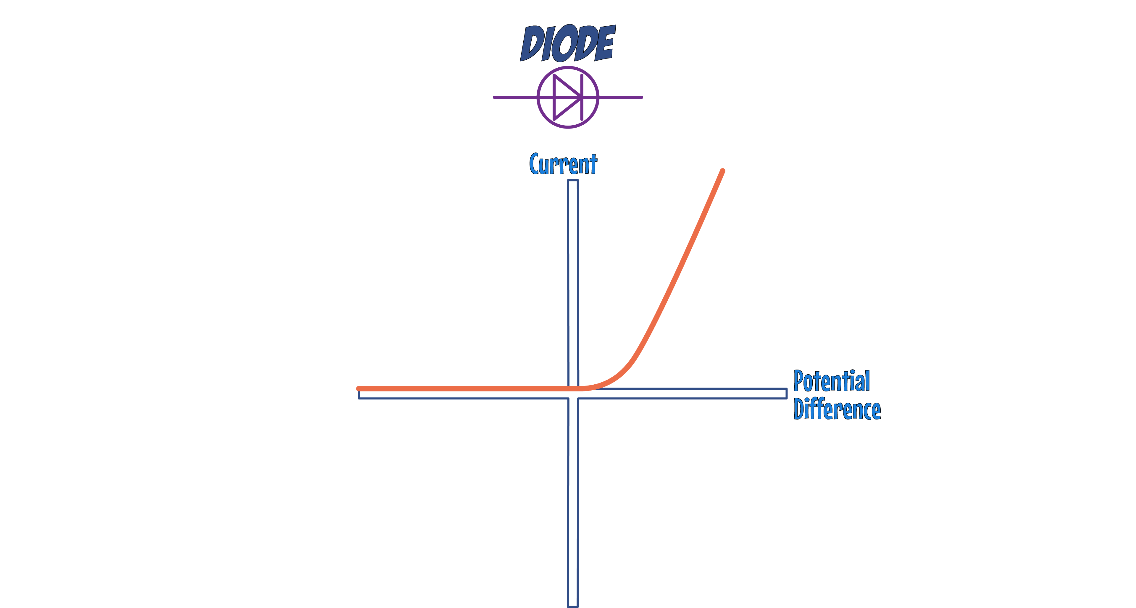
On an I-V graph, current flowing in the CORRECT direction is shown by a sharp increase in current on the POSITIVE AXIS (Right hand side of the graph)
When the diode is connected in the OPPOSITE DIRECTION (left hand side of the graph), the graph is FLAT at 0, indicating NO CURRENT flowing.
OTHER GRAPHS
1. LIGHT-DEPENDENT RESISTORS (LDRs)

An LDR is a resistor whose resistance varies according to the LIGHT INTENSITY of the surroundings:
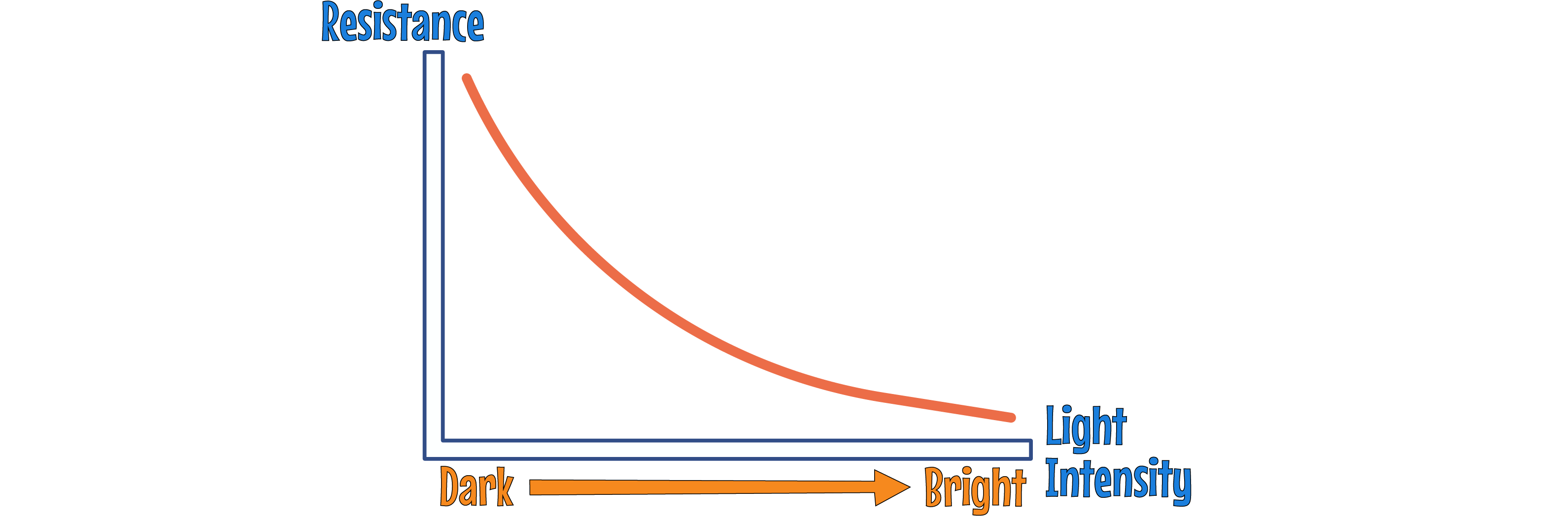
- In BRIGHT LIGHT, the resistance of an LDR decreases, allowing more CURRENT (I) to pass through.
- In DARKNESS, the resistance increases, reducing the current flow.
- LDRs are widely used in devices that react to light conditions, such as AUTOMATIC NIGHT LIGHTS, OUTDOOR LIGHTING, and BURGLAR DETECTORS.
2. THERMISTORS

A THERMISTOR is a resistor that changes its resistance according to the TEMPERATURE of the surroundings:
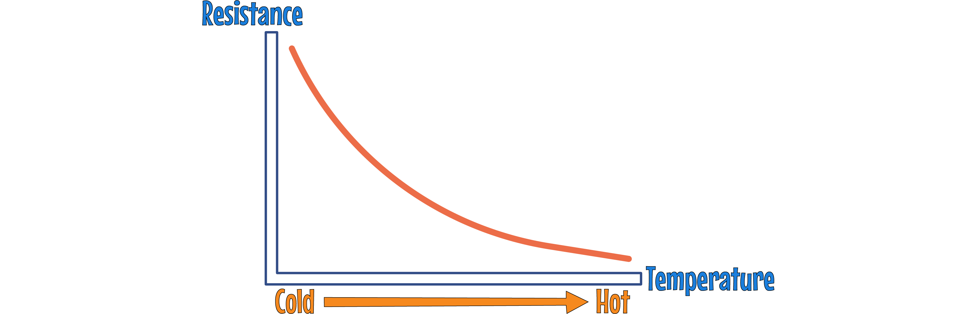
- When it's HOT, the resistance of a thermistor decreases, letting more current through.
- In COOL environments, the resistance increases, reducing the current.
- Thermistors are integral in TEMPERATURE DETECTORS, such as CAR ENGINE SENSORS and ELECTRONIC THERMOSTATS.